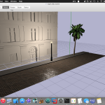
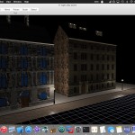
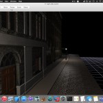
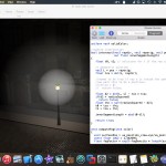
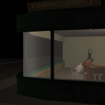
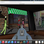
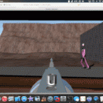
So asset creation in the form of modeling the final environment that’ll be used in the game took the past few days. It’s amazed how much faster it went this time compared the first scene (the city street). I chalk this up to experience that I’ve picked up now that I’ve been doing this awhile, and my understanding of things that are very time consuming to model vs things I can quickly grab, import, texture, and place from turbosquid. The perfect balance of both techniques has led to me being done with the dark night alley street scene after just a few days.
Where I spent the most time this time was in the shaders. I really wanted to have quality rendering and go out with a bang since this’ll likely be the last environment that I do for the game. I want the dark alleyway to appear foggy and dark, like its just about to rain. That includes moist shiny cobblestone rocks, and a damp fog effect that feels very palpable to the player.
This idea of mine posed two major problems that I haven’t had to tackle until now.
Point Light Shadows
The first major problem, is that I could no longer “cheat” using a single directional light source representing the “sun” in the scene. Instead, I had to place a street lamp every building or so and have these be the only sources of light in the scene. This means, in order to keep my shadows working, I now had to implement shadows from a point light source. In some ways this was easier than point lighting (no longer necessary to compute an optimal shadow bounding box to be used for the light’s ortho matrix projection). However, now I needed render to and utilize cube maps to store the shadow depth information. Surprisingly, there was very little comprehensive information on the web about how to properly do PCF shadows using cubemaps.
What I found that works is the following.
- Create a cubemap renderer that is positioned at the exact same position as one of the point lights - this special vgl engine object renders the scene into 6 faces of a cubemap with 90-degree fov angles to properly capture the entire scene from “all angles”.
- Format the cubemap shader to have each face hold floating point depth-component values and keep the size small (256×256) since there will be alot of these.
- Define an “override” shader to be used by the above cubemap renderer to ensure a simple specialized “light render” shader was used when rendering the scene into the cubemap faces.
- Set the cubemap compare mode (GL_TEXTURE_COMPARE_MODE) for the rendered cubemap texture to GL_COMPARE_REF_TO_TEXTURE which helps with percentage-closest-filtering (PCF) mode to allow smoother linear-interpolated shadow edges.
- Lastly, pass a rendered shadow cubemap for each light to the scene shaders in the form of samplerCubeShadow
The “light render” shader mentioned above which is used when rendering the depth information to the cubemaps looks like so:
|
1 2 3 4 5 6 7 8 9 10 11 12 13 14 15 16 17 18 19 20 21 22 23 24 |
precision mediump float;
in mediump vec4 w_pos;
out vec4 fragColor;
struct Light
{
vec4 worldPosition;
};
uniform Light lights[8];
#define LIGHT 0
uniform vec2 nearFarPlane;
void main()
{
// distance to light
float distanceToLight = distance(lights[LIGHT].worldPosition.xyz, w_pos.xyz);
float resultingColor = (distanceToLight - nearFarPlane.x) /
(nearFarPlane.y - nearFarPlane.x);
gl_FragDepth = resultingColor;
fragColor = vec4(1.0);
} |
Basically this encodes the distance from the surface point to the light in the form normalized depth information. This is done by manually overriding the depth value stored in gl_FragDepth. Each light has its own cubemap renderer with a custom-tailored shader like this (using the correct light index to compute distance from).
The per-fragment lighting shader code that utilizes the cube shadow maps looks like:
|
1 2 3 4 5 6 7 8 9 10 11 12 13 14 15 16 17 18 19 20 21 22 23 24 25 26 27 28 29 30 31 32 33 34 35 36 37 38 39 40 41 42 43 44 45 46 47 48 49 50 51 52 53 54 55 56 57 58 59 60 61 62 63 64 65 66 67 68 69 70 71 72 73 74 75 76 77 78 |
/*....*/
#define LIGHT 0
#define ATTENUATION
uniform samplerCubeShadow shadowMap;
/*.......*/
void pointLight0(in mediump vec3 normal, in mediump vec3 eye, in mediump vec3 ecPosition3)
{
mediump float nDotVP; // normal . light direction
mediump float nDotHV; // normal . light half vector
//mediump float pf = 0.0; // power factor
mediump float attenuation = 1.0; // computed attenuation factor
mediump float d; // distance from surface to light source
mediump vec3 VP; // direction from surface to light position
mediump vec3 halfVector; // direction of maximum highlights
// Compute vector from surface to light position
VP = vec3(lights[LIGHT].position) - ecPosition3;
#ifdef ATTENUATION
// Compute distance between surface and light position
d = length(VP);
#endif
// Normalize the vector from surface to light position
VP = normalize(VP);
// Compute attenuation
#ifdef ATTENUATION
{
attenuation = 1.0 / (lights[LIGHT].constantAttenuation +
lights[LIGHT].linearAttenuation * d +
lights[LIGHT].quadraticAttenuation * d * d);
}
#endif
nDotVP = dot(normal, VP);
mediump vec2 frontAndBack = vec2(nDotVP, -nDotVP);
frontAndBack = max(vec2(0.0), frontAndBack);
float visibility = 1.0;
// difference between position of the light source and position of the fragment
vec3 fromLightToFragment = lights[LIGHT].worldPosition.xyz - va_position.xyz;
// normalized distance to the point light source
float distanceToLight = length(fromLightToFragment);
float currentDistanceToLight = (distanceToLight - nearFarPlane.x) / (nearFarPlane.y - nearFarPlane.x);
// normalized direction from light source for sampling
fromLightToFragment = normalize(fromLightToFragment);
visibility *= max(texture(shadowMap, vec4(-fromLightToFragment, currentDistanceToLight-shadowBias), 0.0), 0.0);
// if(nDotVP > 0.0)
{
diffuse += visibility*material.diffuse*lights[LIGHT].diffuse * frontAndBack.x * attenuation;
diffuseBack += visibility*material.diffuse*lights[LIGHT].diffuse * frontAndBack.y * attenuation;
}
//if(lights[LIGHT].doSpec)
{
mediump vec2 cutOff = step(frontAndBack, vec2(0.0));
halfVector = normalize(VP + eye);
nDotHV = dot(normal, halfVector);
frontAndBack = vec2(nDotHV, -nDotHV);
frontAndBack = max(vec2(0.0), frontAndBack);
lowp vec2 pf = pow(frontAndBack, vec2(material.shininess, material.shininess));
specular += visibility*material.specular*lights[LIGHT].specular * pf.x * attenuation * cutOff.y;
specularBack += lights[LIGHT].specular * pf.y * attenuation * cutOff.x;
}
ambient += lights[LIGHT].ambient * attenuation;
} |
Essentially the highlighted code above compares the distance between the surface point to the light to the stored depth value in the cube texture using the fragment-light vector as a lookup value into the cubemap. Because we’re sampling using a special “shadow” version of the cubemap sampler, the result will be properly interpolated between shadow texels to avoid ugly edges between shadowed and non-shadowed areas.
Luckily, I was able to build this into the Verto Studio editor and associated graphics system and test this out with relatively little trouble. Even though I have 4 or 5 statically rendered cubemap shadow textures in the entire scene. I was able to keep performance high by building versions of the shaders for each side of the street so that each individual shader only has to shade with at most 3 lights at a time. This worked out better than I had expected.
Light-Fog Interaction (Volume FX)
This part was tricky.. I had an idea in my head of how I wanted this to look. So I did something that usually leads to trouble; I tried to come up with a volume rendering technique on my own from scratch and implement it and just kinda see how it goes.
The basic idea stems from what I’ve observed in real life from foggy, dark, damp nights and lighting. Essentially, fog at night is black… IF there is no light around to interact with the fog. Naturally, if the water droplets don’t have any light to interact with them, you won’t see them and the fog will appear black. However, if any light interacts with the water vapor in the air, it’ll create the illusion of a whiter colored and denser fog. So this is what I set out to emulate with my shader.
Now atmospheric shader effects can often lead to the necessity of raymarching and heavy iteration in the fragment shader to simulate the accumulation of light-atomosphere interaction. To this I said “hell no” since ray marching of any kind in a shader terribly robs performance. I quickly realized that I could avoid raymarching entirely if I used a simple model to represent the light-fog interaction that I was going for.
In my case, it turned out I could do the whole effect using something as simple as a sphere intersection test. Basically, when I’m shading a pixel (a point on the surface), I’m interested in what happens to the light on its way back from the surface to the viewer, the surface-to-viewer vector. If the atmosphere affects the light at any point along this vector, I’ll need to compute that. In other words, if the ray from the surface to the viewer intersects a sphere centered at the light, then the fog affects the light on the way back to the viewer. How much? Well if I calculate the length of the segment between the entry and exit points of the ray intersection (how much of the sphere the ray pierces), I find that length is proportional to both the perceived increase in density of the fog and the brightening of the fog color.
This algorithm is given below in fragment shader code:
|
1 2 3 4 5 6 7 8 9 10 11 12 13 14 15 16 17 18 19 20 21 22 23 24 25 26 27 28 29 30 31 32 33 34 35 36 37 38 39 40 41 42 43 44 45 46 47 48 49 50 51 52 53 54 55 56 57 58 59 60 61 62 63 64 65 66 67 68 69 70 71 72 73 74 75 76 77 78 79 80 81 82 83 84 85 |
/*.....*/
uniform float fogDensity;
uniform vec3 fogColor;
//sphere intersection
bool intersect(vec3 raydir, vec3 rayorig, vec3 pos, float radiusSquared,
out float innerSegmentLength)
{
float t0, t1; // solutions for t if the ray intersects
// geometric solution
vec3 L = pos - rayorig;
float tca = dot(L, raydir);
//seems to be true if ray o is inside the sphere
//we want this to be a positive..
//if(tca < 0)
// return false;
float d2 = dot(L, L) - tca * tca;
if(d2 > radiusSquared)
return false;
float thc = sqrt(radiusSquared - d2);
t0 = tca - thc;
t1 = tca + thc;
innerSegmentLength = abs(t0-t1);
return true;
}
vec4 computeFog(vec4 color)
{
vec3 viewDirection = normalize(cameraPosition - vec3(va_position));
vec3 surfacePos = ec_pos.xyz/va_position.w;
const float LOG2 = 1.442695;
float fogFactor = exp2(-fogDensity * length(surfacePos) * LOG2);
vec3 fogCol = fogColor;
vec3 rayO = vec3(va_position);
vec3 rayD = viewDirection;
float len = 0.0;
const float r = 80.0;
//for each light we interact with...
if(intersect(rayD, rayO, lights[LIGHT].worldPosition.xyz, r*r, len))
{
float d = len/r;
float p = clamp(log(d)*d, 0.0, 1.0);
fogCol = mix(fogColor, vec3(0.4), p);
len = 0.0;
const float innerR = 25.0f;
if(intersect(rayD, rayO, lights[LIGHT].worldPosition.xyz, innerR*innerR, len))
{
float len10 = len/innerR;
float nd = min(len10*0.25, 1.0);
fogFactor *= mix(1.0, 0.0, nd);
fogCol += mix(vec3(0.0), vec3(0.2), len10);
}
}
if(intersect(rayD, rayO, lights[LIGHT1].worldPosition.xyz, r*r, len))
{
float d = len/r;
float p = clamp(log(d)*d, 0.0, 1.0);
fogCol = mix(fogColor, vec3(0.4), p);
len = 0.0;
const float innerR = 25.0f;
if(intersect(rayD, rayO, lights[LIGHT1].worldPosition.xyz, innerR*innerR, len))
{
float len10 = len/innerR;
float nd = min(len10*0.25, 1.0);
fogFactor *= mix(1.0, 0.0, nd);
fogCol += mix(vec3(0.0), vec3(0.2), len10);
}
}
return mix(vec4(fogCol, 1.0), color, fogFactor);
} |
I’m sure I’m not the first one to come up with this idea before, but it still did feel pretty cool to reason my way through a shading problem like this. The visual result looks amazing.
The progress of this all is below in a gallery.
